
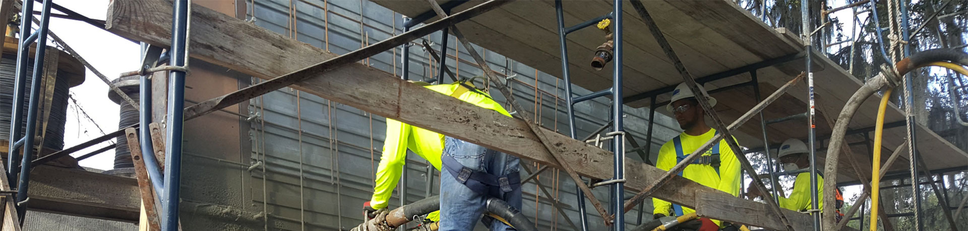
When considering placement options for thick section overhead concrete repair or strengthening, more often than not, the consideration of a shotcrete solution is overlooked. Historically, shotcrete has suffered from being mainly associated with vertical placements for above ground work. This may be due to the fact that until 1983, silica fume enhanced shotcrete was unheard of in North America; therefore, building up placement lifts overhead of more than a few inches thick using shotcrete was not deemed possible. Additionally, many shotcrete contractors customarily have avoided low production applications where placement volumes are measured in cubic yards per day rather than cubic yards per hour. As a result, most thick overhead concrete sections have been placed via the more common method of forming and pumping.
In general, forming and pumping concrete overhead works adequately. In deep sections the concrete or repair material is pumped through a port or valve on the bottom or lower side of the stout form. In effect, the air inside the form is pushed up and ultimately out of the concrete placement location. In deep section repair, there can be challenges devising a methodology that ensures no air is trapped in the upper sections of prepared areas. Repairs to pile caps may preclude the coring of vent holes down through the top of the deck due to congestion of reinforcing steel. In a form and pump application, the issue of adequate bond to the prepared concrete substrate is also a consideration. Most repair installations require a composite action of new material to existing concrete. Curing, shrinkage, and the presence of bleed water floating on top of the new concrete placement may adversely affect the ultimate bond strength of these installations. The aspect of building forms for repair and strengthening placements, especially around precast piling, can be difï¬cult and extremely time consuming as well.
Careful consideration of the pros and cons of shotcrete placement over a more traditional approach of forming and pumping for thick overhead sections offers compelling technical evidence for pursuing a shotcrete option. The following case
Safety and Common Sense
Often when the subject of safety is brought up, we start thinking of regulations, special protective equipment, programs, inspections, reporting, meetings, insurance, and so on. Common sense tells us that it is in our best interests to have good safety practices and to enforce company safety policies. However, sometimes our attitude toward safety is not very positive, treating safety programs and policies as a necessary evil rather than a critical part of daily operations. Having a safe work place starts with instilling a positive attitude in all employees. Doing even the simplest things safely creates an atmosphere that tells employees that the company is concerned about them beyond what is required by law.
Let™s look at two examples”one obvious, and one less apparent:
Innovative Synthetic Fibers
After four years of research and development on improving the bonding capabilities of synthetic ï¬bers, we recently patented a high-tensile-strength synthetic ï¬ber that partially ï¬brillates upon mixing and shooting, increasing its ï¬nal surface area and bonding capabilities to the concrete.1 The ï¬bers are introduced into the concrete mixer as monoï¬lament units of relatively low surface area (F4-a in Fig. 1), allowing up to 2% vol. (18.5 kg/m3 [31.2 lb/yd3]) ï¬ber dosages. During the mixing process, each ï¬ber transforms into a unit having several ï¬brils at its ends (F4-b in Fig. 1). The ï¬brils anchor each ï¬ber so their bonding capabilities are superior to those of
Shotcrete Foundation Walls at the Smithsonian Portrait Gallery in Washington, DC
The National Portrait Gallery, located on the campus of the Smithsonian Institution in Washington DC, is one of the oldest government buildings in that historic city. It was the original location for the U.S. Patent Office and it was used as the site of the inaugural ball celebrating the election of Abraham Lincoln in January 1861. When a recent renovation and expansion project was started on the building, shotcrete was selected as the material of choice
Use of Fiber-Reinforced Shotcrete
As many of you Shotcrete readers know, there have been many articles published here on FRS, and many more where FRS is mentioned. Two articles in the premier issue of Shotcrete in February, 1999, mentioned FRS. I have been keeping a bibliography of Shotcrete articles on FRS and, through Summer 2004, I have over 20 listed. These, of course, are available on the American Shotcrete Association (ASA) website. For example, in an editorial in the May 2000 issue, Mike Ballou says, œSteel Fiber Reinforced Concrete”It is time to ï¬ nd out about it, and in a Spring 2003 Technical Tip, Denis O™Donnell discusses where ï¬ bers should or should not be used in ground support for hard rock mining.
Waterproofing Your Shotcrete Tank
When it comes to preventing water damage and preserving the integrity of concrete structures, waterprooï¬ ng is essential. In of concrete tanks, however, effective, reliable waterprooï¬ ng is especially critical. Concrete tanks play a vital role in many communities. They function as drinking water containers, wastewater treatment plants, and water storage reservoirs. Not only is a leak in a facility like this expensive and time-consuming to repair, it can be inconvenient and even dangerous to the community.
High Cost of Steel Not the Only Reason for Using Fibers as Shotcrete Reinforcement
The rising cost of conventional steel reinforcement has dramatically increased the demand for synthetic, as well as steel, ï¬bers as an alternative to wire mesh in shotcrete applications. More importantly, with the shift to the shotcrete industry is discovering that reinforcement yields signiï¬cant economic advantages, as well as definite engineering benefits for long-term shotcrete durability.
Signiï¬cant economic beneï¬ts result from the elimination of placing wire mesh. In addition, the use of ï¬brous reinforcement in lieu of wire mesh reduces rebound from the receiving face by up to 20%.
Suitable shotcrete applications include slope stabilization, tunnel liners and water diversion channels, structural repairs, swimming pools, arti-ï¬cial rock, waterscapes, and thin overlays. These applications beneï¬t from the three-dimensional network of reinforcement formed by the ï¬bers, which reduces plastic shrinkage cracking and drying shrinkage cracking. The ï¬bers also provide quanti-ï¬able toughness and enhanced durability, including increased surface abrasion resistance and impact resistance. Performance is predicated on the proper selection of the ï¬ber type, length, conï¬guration, and addition rate. Elimination of potential voids created by the wire mesh pattern is just one more advantage of using ï¬ber.
General Product Information
There are three ï¬ber types that contribute to the physical properties of shotcrete: steel ï¬bers, micro- synthetic ï¬bers, and macro-synthetic ï¬bers.
Although the price of steel ï¬bers has risen, the fact remains that the in-place cost of steel ï¬ber-reinforced shotcrete is less than the cost of ï¬xing and placing conventional steel. In general, steel ï¬bers must meet the requirements of ASTM A 820 and may be manufactured from either drawn wire or slit sheet steel. Steel ï¬bers, ï¬rst introduced in the mid 1970s, are generally available in four lengths: 3/4, 1, 1-1/2, and 2 in. (20, 25, 38, and 50 mm). The standard unit of sale is typically 50 lb (22.7 kg) boxes or bags.
Micro-synthetic ï¬bers can be nylon mono-filament or polypropylene monofilament and ï¬brillated ï¬bers. They have been in use since the early 1980s for secondary temperature-shrinkage
Waterproofing and Concrete Restoration at Blackwater Dam
One of the oldest dams in New England, the Blackwater Dam in Webster, NH, is located approximately 8.6 mi above the confluence of the Blackwater and Contoocook Rivers. It is part of a network of ï¬ve flood-control dams in the Merrimack River Basin that work together to control flood waters during heavy rains and storms until rivers begin to drop and the stored water can be slowly and safely released. The reservoir has a storage capacity of 15 billion gal. of water.
The U.S. Army Corps of Engineers (USACE), who oversees the property, engaged The Aulson Company to complete major concrete repairs and waterprooï¬ng to restore the dam and pedestrian walkway to peak condition after 60 years of deterioration. The USACE had made previous attempts at restoration but was not satisï¬ed with the results.
The Restoration Challenge
When the Blackwater Dam was built in 1941, the technology used to mitigate expansion and contraction was to install horizontal and vertical joints. No weepholes were provided in the original design to allow drainage back to the channel, so
Concrete Repair and Restoration at Franklin Falls Dam
The Aulson Company of Methuen, MA, completed a major concrete removal, shotcrete repair, and restoration project for the U.S. Army Corps of Engineers (USACE) at the Franklin Falls Dam, a 60-year-old structure in Franklin, NH. The Franklin Falls Dam was built by the USACE as part of a coordinated system of reservoirs to provide flood control on the Pemigewasset River Watershed of the Merrimack River Basin in the state of New Hampshire. Authorized by the Flood Control Act of 1936, the project is located on the Pemigewasset River, the main tributary of the Merrimack River, approximately 2.5 mi upstream from the city of Franklin, NH. Construction of the project began in November 1939 and was completed in October 1943. The reservoir is operated for flood control and has a total storage capacity of 154,000 acre-ft. The dam is constructed of rolled earth ï¬ll, with protective rip rap, rising 140 ft above the river bed. The spillway consists of an excavated channel along the westerly
Shotcrete Repair of WWII Concrete Hulks
In response to a shortage of plate steel during the Second World War, the United States Maritime Commission ordered 24 ships and 58 barges to be constructed with lightweight concrete. The ships were typically about 336 ft (110 m) long with a beam of 54 ft (16.5 m) and a displacement of about 11,000 tons (10,000 t). These ships and barges performed various levels of military service but typically for relatively short times due to several factors, not the least of which was the end to hostilities shortly after their launches. The useful service of these vessels (as ships and barges) was measured in months, with some being decommissioned immediately after delivery. However, at Powell River in British Columbia, Canada, as a floating breakwater and impoundment for the log storage pond, most of the surviving hulks have over 50 years of service in a saltwater environment. The Powell River floating breakwater is comprised of seven WWII steam-ships, two WWII barges, and one WWI steamship. The paper mill in Powell River acquired these ships between 1948 and 1966. After their arrival, the ships were stripped of amenities and machinery and the hulks placed in service as a breakwater.
For most of the hulks™ life as a breakwater, they were protected from direct barge impact by the numerous logs floating in the storage pond deï¬ned by the hulks. With the changing operations of the mill and the removal of the logs, the hulks became vulnerable to impact by barges also operating in the pond. This article describes the recent shotcrete repair of the impact damage to some of the hulks.
Need for Repair
While the hulks are showing deterioration related to the corrosion of the reinforcing steel due