On August 14, 2021, the Caldor Fire started in Northern California near Pollock Pines, CA. The fire ended up consuming almost 222,000 acres (90,000 hectares) and seriously threatened South Lake Tahoe. Besides the over 1000 structures that were lost, the fire also burned along a major portion of the El Dorado Irrigation District’s Canal (EID) which provides drinking and irrigation water to numerous communities throughout the area
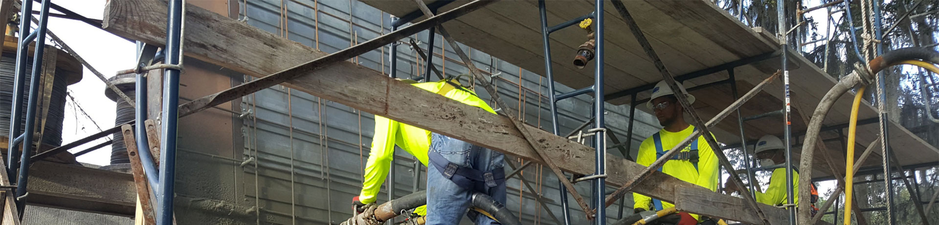
SHOTCRETE AT MT PLEASANT STATION
Multi-million dollar underground stations are currently under construction on Metro and LRT lines in Toronto, Ontario, Canada. Traditionally, the thick, heavily reinforced structural concrete station walls have been constructed using the conventional form-and-pour concrete construction method. This construction method, while widely used, is not without its challenges.
Many of the underground station sites are in congested urban areas with limited spaces for laydown of concrete formwork, and crane access time for handling and installation of formwork is often on a critical path for completion of station construction.
HIGHLINE GARIBALDI SPRINGS ROCKSCAPE RETAINING WALL
This retaining wall was contracted for a new townhouse development project in Squamish, BC, Canada. Vancouver Shotcrete & Shoring Inc. has serviced many municipalities and private companies over the past 30 years in the fields of shotcrete shoring, pools, and custom rockscapes.
The shotcrete retaining wall was designed to be anchored by Titan 40 self-drilling anchors with a test load capacity of 52,000 lbs (24,000 kg) each, spaced every 6 ft (2 m) on center. The temporary 4 in. (100 mm) shotcrete was reinforced with 4 x 4 x 1 in. (100 x 100 x 25 mm) welded wire mesh, with a 0.8 in. (20 mm) continuous whaler lining to span the load between each anchor. The engineer specified a 5800 psi (40 MPa) shotcrete mix for this purpose.
Outstanding Infrastructure Project
I have a project with a segmental retaining wall. The project is located in Maryland. The CMUs of the retaining wall have significantly deteriorated in several areas. The geo-grid fabric appears to be in good condition in the areas where it could be observed. I suspect the deterioration is caused by saltwater runoff during snow events combined with the freeze/thaw cycles. There are some localized areas where the masonry units have completely disintegrated. The largest area being approximately 4 ft2 (0.37 m2). Is it feasible to remove the deteriorated masonry material, down to a sound surface, and shotcrete the face to restore (or exceed) the structural integrity of masonry units? If so, will this restore the structural integrity of the segmental retaining wall?
Shotcrete is routinely used for the repair of deteriorated concrete masonry and brick. Shotcrete should easily have a minimum compressive strength of 4000 psi (28 MPa) when properly shot and cured. According to the National Concrete Masonry Association, current CMU units have a minimum 2000 psi (14 MPa) compressive strength. Older CMU had a lower 1500 psi (10 MPa) minimum. Thus, the shotcrete placement will be significantly stronger and less permeable than the in-place CMU. This should give the wall better resistance to saltwater and freeze-thaw exposures thus extending useful life.
Depending on the depth of the new shotcrete placement, you may consider mechanically tying the shotcreted layer back to the sound CMU with epoxy or mechanically embedded anchors or j-bolts. Thicker sections may also benefit from the use of a steel wire mesh or fibers.
When shooting onto existing CMU sections, the surface must be properly prepared and then shotcreted with proper shotcrete materials, equipment, and placement techniques. Shotcrete placed onto an existing CMU surface will provide an excellent bond IF the following conditions are met:
- Make sure the surface is roughened and clean.
- The amplitude of roughness should be +/- 1/8th in. (3 mm) or more.
- A high-pressure water blaster (5000 psi [34 MPa] or more) or abrasive blasting can help to roughen and clean the surface.
- Bring the CMU surface to a saturated surface dry (SSD) condition. This means the surface feels damp, but water is not picked up on a hand.
- Make sure the shotcrete placement is properly executed with high-velocity placement and quality materials.
- The shotcrete should have a minimum 28-day compressive strength of 4000 psi (28 MPa).
- Be sure the shotcrete contractor is using an air compressor able to produce at least 185 CFM (5.2m3/min) for wet-mix and 375 CFM (10.6 m3/min) for dry-mix (gunite) of air flow at 100 to 120 psi (0.7 to 0.8 MPa).
- Use of an ACI-certified shotcrete nozzleman is recommended.
- No bonding agent should be used. It will interfere with the natural bonding characteristics of shotcrete placement.
Finally, without details on the loading conditions, and structural details of the original construction, we cannot comment on the structural integrity of the repaired wall. You should contact a professional engineer experienced in concrete repair to evaluate the structural integrity of the wall when repaired.
Mount Pleasant Station, Part 1: Preconstruction Qualification for Shotcreting of Mass Concrete
Multi-million-dollar underground stations are currently under construction on Metro and LRT lines in Toronto, Ontario, Canada. Traditionally, the thick, heavily reinforced structural concrete station walls have been constructed using the conventional form-and-pour concrete construction method. This construction method, while widely used, is not without its challenges.
#1 – Compressive (Strength) Values of Pool Shotcrete
Download#2 – Definitions of Key Shotcrete Terminology
Download#3 – Sustainability of Shotcrete in the Pool Industry
Download#4 – Watertight Shotcrete for Swimming Pools
Download#5 – Monolithic Shotcrete for Swimming Pools (No Cold Joints)
Download#6 – Forming and Substrates in Pool Shotcrete
Download#7 – Curing of Shotcrete for Swimming Pools
Download#1 – Spraying Shotcrete Overhead in Underground Applications
Download#2 – Spraying Shotcrete on Synthetic Sheet Waterproofing Membranes
Download#3 – Encapsulation of Reinforcement in Tunnel Shotcrete Final Linings
DownloadASA Outstanding Shotcrete Awards Program
The ASA Outstanding Shotcrete Project Awards Program exists to recognize excellence and innovation on projects in which the application of shotcrete has played a significant role.
ASA’s Annual Outstanding Shotcrete Project Awards Program provides an exciting real-world demonstration of the exceptional advantages of placing concrete via the shotcrete process. Many sustainability advantages are also inherent in the shotcrete process and play a significant role in winning projects as well as the project owner’s ultimate decision to use shotcrete as the method of concrete placement. Projects must be completed between January 1, 2022, through September 1, 2024, and can be submitted in the following areas: Architecture │ New Construction, Infrastructure, International Projects, Pool & Recreational, Rehabilitation & Repair, and Underground.
To assist in your submission, we have provided submission resources to inform you of the submission guidelines, a list of questions, and a copy of the owner release form. Please email any questions to [email protected].
Award Archive
2025 – Twenty First Annual Outstanding Shotcrete Project Awardees
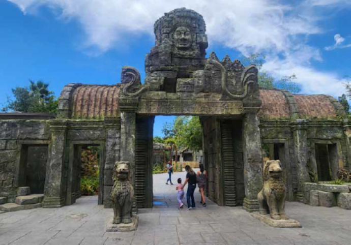
Outstanding Architecture
Fresno Chaffee Zoo: Kingdoms of Asia | Fresno, CA
Project Name:
Fresno Chaffee Zoo: Kingdoms of Asia
Location:
Fresno, CA
Shotcrete Contractor:
COST of Wisconsin*
Architect/Engineer:
CLR Design / Patrell Engineering
Material Supplier/Manufacturer:
Builders Concrete Inc. & Outback Concrete
Equipment Manufacturer:
REED Shotcrete Equipment*
General Contractor:
Bernards Bros
Project Owner:
Fresno Chaffee Zoo
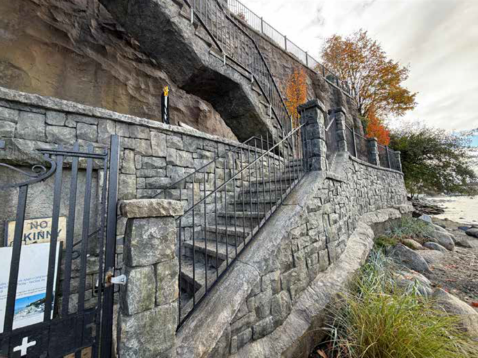
New Construction Project
Point Grey Shoreline Stability | Vancouver, BC, Canada
Project Name:
Point Grey Shoreline Stability
Location:
Vancouver, BC, Canada
Shotcrete Contractor:
Ocean Rock Art LTD*
Architect/Engineer:
Paul Sangha Creative
Material Supplier/Manufacturer:
Heidelburg Materials
Equipment Manufacturer:
Putzmeister*
General Contractor:
GWilson Construction
Project Owner:
Claire and Jaime Wright
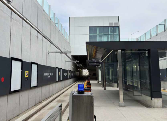
Outstanding Infrastructure Project
Humber College Station | Toronto, ON, Canada
Project Name:
Humber College Station
Location:
Toronto, ON, Canada
Shotcrete Contractor:
Consolidated Shotcrete Inc.*
Architect/Engineer:
Arup
Material Supplier/Manufacturer:
Dufferin Concrete
Equipment Manufacturer:
Western Shotcrete Equipment*
General Contractor:
Mosaic Transit Group Joint Venture (Aecon Infrastructure and Management Inc., Dragados Canada Inc., Dufferin Construction Company)
Project Owner:
Metrolinx
Outstanding International Project
National Route N2 Slope Stabilization | Eastern Cape, South Africa
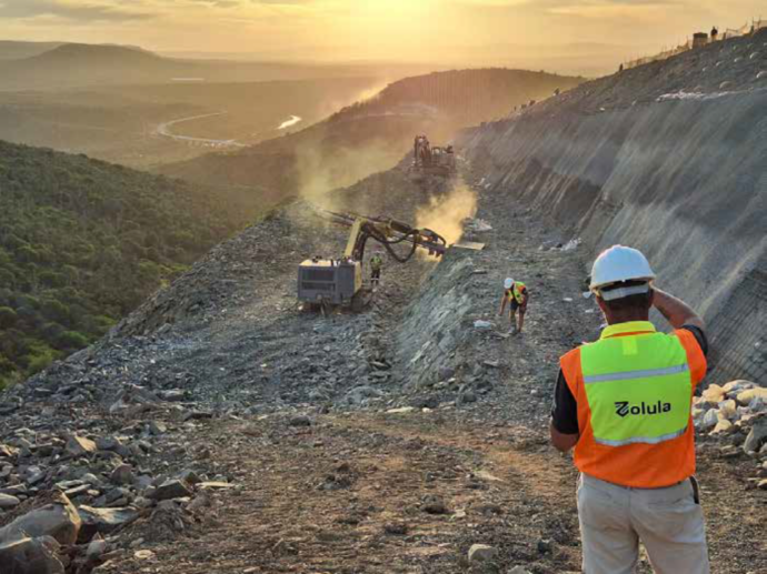
Project Name:
National Route N2 Slope Stabilization
Location:
Eastern Cape, South Africa
Shotcrete Contractor:
Zolula (Pty) Ltd*
Architect/Engineer:
Bosch Projects / AGES-Group
Material Supplier/Manufacturer:
WBHO Construction
Equipment Manufacturer:
Putzmeister*
General Contractor:
WBHO Construction
Project Owner:
South African National Roads Agency SOC Ltd
Outstanding Pool & Recreational Project
Southern Living Pools | Horseshoe Bay, TX
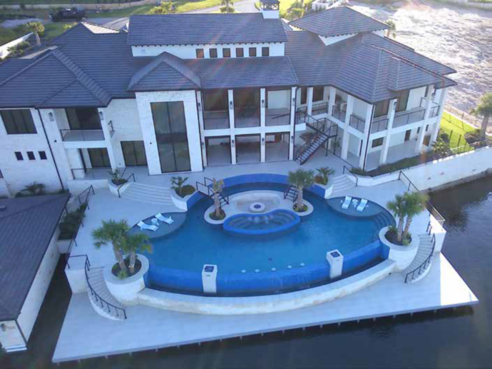
Project Name:
Southern Living Pools
Location:
Horseshoe Bay, TX
Shotcrete Contractor:
Texan Concrete Construction Solutions, LLC dba – Texan Gunite*
Architect/Engineer:
Smith Engineering – Austin, TX
Material Supplier/Manufacturer:
Texan Concrete Construction Solutions, LLC dba – Texan Gunite*
Equipment Manufacturer:
Putzmeister America*
General Contractor:
Jeff Jackson Homes
Project Owner:
Southern Living Pools
Outstanding Rehabilitation & Repair Project
Abitibi Canyon Z7 Dam Rehabilitation | Abitibi Canyon, ON, Canada
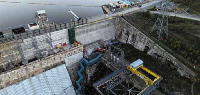
Project Name:
Abitibi Canyon Z7 Dam Rehabilitation
Location:
Abitibi Canyon, ON, Canada
Shotcrete Contractor:
SWATcrete*
Architect/Engineer:
Atkins Realis
Material Supplier/Manufacturer:
L. Fournier & Fils Inc*
Equipment Manufacturer:
SWATcrete* (Customized Aliva 252)
General Contractor:
PETER KIEWIT SONS ULC
Project Owner:
Ontario Power Generation
Outstanding Underground Project
NYC Grand Central Station New Passageway | New York City, NY
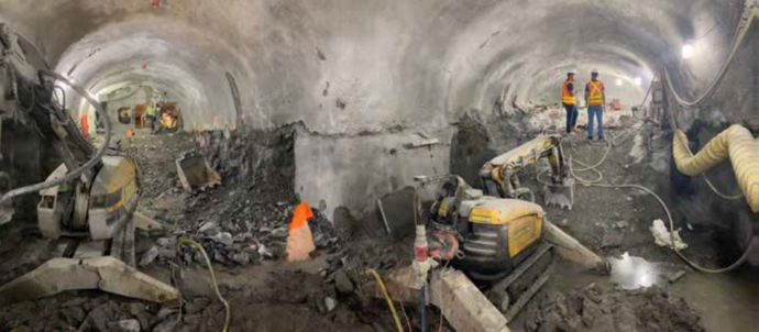
Project Name:
NYC Grand Central Station New Passageway
Location:
New York City, NY
Shotcrete Contractor:
Patriot Shotcrete*
Architect/Engineer:
STV Incorporated
Material Supplier/Manufacturer:
Tec-Crete Transit Mix
General Contractor:
Skanska USA Civil Northeast
Project Owner:
Metropolitan Transit Authority
Honorable Mention Project
Pompeys Pillar National Monument Stabilize | Pompeys Pillar, MT
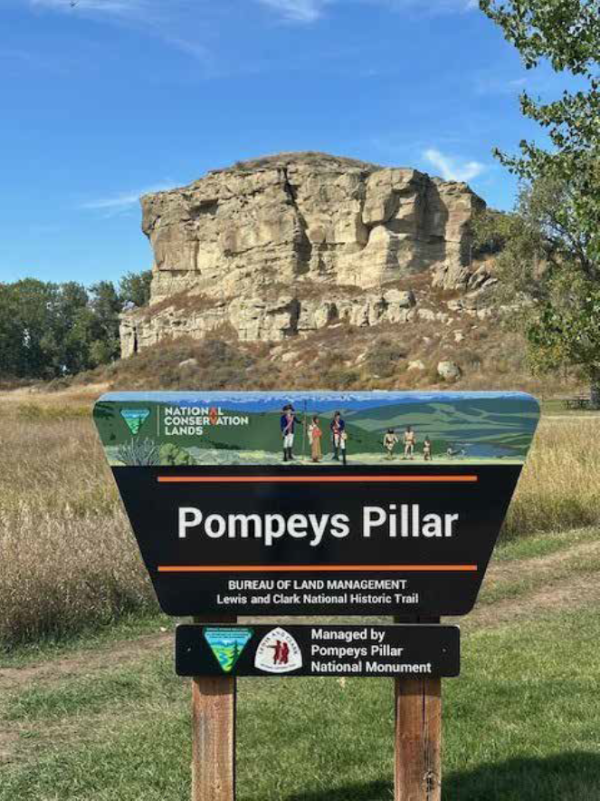
Project Name:
Pompeys Pillar National Monument Stabilize
Location:
Pompeys Pillar, MT
Shotcrete Contractor:
Shotcrete Montana LLC*
Architect/Engineer:
Bureau of Land Management- MT State OFC
Material Supplier/Manufacturer:
The Quikrete Companies*
Equipment Manufacturer:
REED Shotcrete Equipment*
General Contractor:
TripTych Construction LLC
Project Owner:
Bureau of Land Management – MT State OFC
Honorable Mention Project
Business in the Front, Party in the Back | Raleigh, NC
Project Name:
Business in the Front, Party in the Back
Location:
Raleigh, NC
Shotcrete Contractor:
Revolution Gunite*
Architect/Engineer:
Waterforge, Inc
Material Supplier/Manufacturer:
Revolution Gunite*
Project Owner:
Jiten Patel
Pool Contractor:
Raleigh Pools
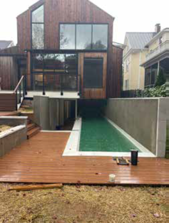
Honorable Mention Project
North America’s Tallest Retained Façade | Toronto, ON, Canada
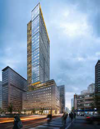
Project Name:
North America’s Tallest Retained Façade
Location:
Toronto, ON, Canada
Shotcrete Contractor:
Green Infrastructure Partners Inc.*
Architect/Engineer:
Grounded Engineering
Material Supplier/Manufacturer:
Canadian Building Materials
General Contractor:
EllisDon Residential
Project Owner:
481 Uni Investments Inc
Mapei’s London Underground Bank Station’s Capacity Upgrade
Deep in the heart of London’s financial centre, work has been continuing to make one of the world’s largest stations safer and easier for passengers to use. Finding your way around the existing labyrinth of tunnels, connecting five London underground lines, is a task worthy of the most experienced navigator.