A well-planned job with a focus on safety will bring profit to your company, and your customers will appreciate a job done on-time and on-budget. Spending the proper time every day pre-planning and ensuring the job is safe will benefit all.

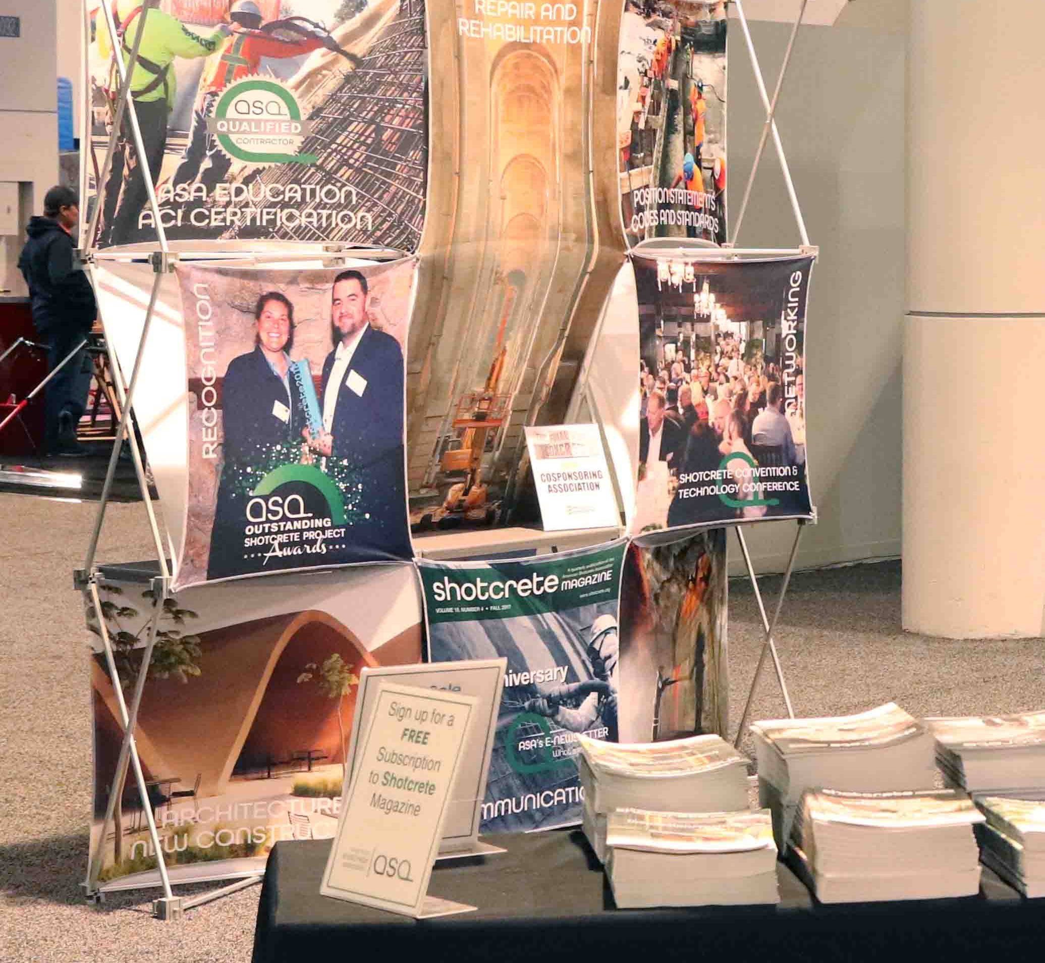
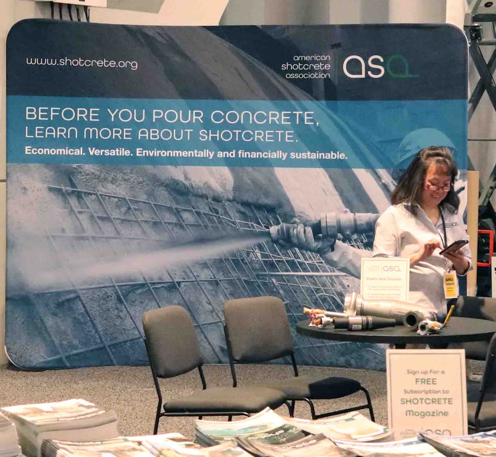
This annual convention is one of the largest events serving the concrete industry! ASA is proud to be a co-sponsor and exhibitor at WOC. Read the post-show press release here. Each year ASA’s exhibit in South Hall provides an opportunity to both reconnect with members and meet new faces in the industry. ASA’s discount code provides the best discounts for Exhibit-Only passes and supports the association. Be sure to check back when registration opens in the Fall!
Here’s a look at ASA’s presence this year! Save the dates for next year: January 19 – 21, 2027!
ASA sponsored events at WOC:


Shotcrete for Repair, Rehabilitation and Re-purposing
Time: 1:00 PM – 2:30 PM
Location: North Hall N241
Speaker: Charles Hanskat
Registration code: M0153 (a new WOC 90-Minute Seminar)
This presentation will provide the owner, design engineer, project specifier, field inspector, specialty subcontractors, and general contractors with an overview of how shotcrete can be efficiently and cost-effectively utilized for the structural repair, rehabilitation, and re-purposing of concrete buildings and infrastructure. We will provide a basic overview of the shotcrete process, cover the design, specifying, and detailing considerations for the design of shotcrete repairs. Next, we will cover field considerations, including reduced formwork needs and scheduling advantages. We will also discuss achieving quality shotcrete placement, addressing field inspection, shooting techniques, shotcreter and inspector certifications, and contractor qualifications. We will conclude with a list of relevant references and resources on using shotcrete for structural concrete repair.

Charles Hanskat
Charles Hanskat, PE, FACI, FASCE, ASA Executive and Technical Director, is also an ASA/ACI Examiner for the wet- and dry-mix processes. Charles also actively serves on a wide range of shotcrete-related committees including ACI and ASTM.
ASA SHOTCRETER (formerly known as Nozzleman) EDUCATION CLASS
Time: 8:00 AM – 4:00 PM
Location: N211
Speaker: Oscar Duckworth
Registration code: ASATU (an Industry Training Course)
Registration Fee: $450; $485 after 12/12/2025
Attendees will receive: CP-60 4th Ed Shotcrete Nozzleman Craftsman Workbook
This 7-hour program is a requirement for all shotcreters wishing to pursue certification as an ACI Shotcreter (formerly known as Nozzleman) through ASA. However, it also provides a great overview of the shotcrete process for contractors and project managers. This registration includes the required CP60 workbook (available in English or Spanish) and a complimentary 1-year ASA Shotcreter membership. (Registering for this class would also require you to sign up for an Exhibit-Only Pass, available for $50 using ASA’s source code: A17. Class is listed under Association and Industry Training.) Please note: this class alone will not result in certification. Opportunity for Wet-Mix certification is available, see Thursday option below.

Oscar Duckworth
Oscar Duckworth is ACI Certified Shotcreter and currently an ASA/ACI Examiner for the wet- and dry-mix processes.
ASA WOC 2026 General Membership Meeting & Shotcrete Reception
Time: 5:00 PM – 7:30 PM
Location: S223
Come hear the latest updates on ASA’s activities and network at our General Membership Meeting and Reception (included with WOC Exhibit-Only registration).
QUALITY SHOTCRETE – Know It When You See It (Shotcrete Inspector Education)
Times: 8:00 AM – 4:00 PM (course) • 4:00 PM – 6:00 PM (exam)
Location: N211
Speakers: Oscar Duckworth & Charles Hanskat
Registration Code: ASAWE (seminar only); ASAWEX (seminar with exam) (an Industry Training Course)
Registration Fee: Course only: $450; $485 after 12/12/2025 | Course with exam: $680; $715 after 12/12/2025
With the strong growth of shotcrete construction, the concrete construction industry needs on-site inspectors who are knowledgeable about producing high-quality and durable shotcrete. This one-day session from ASA provides guidance on over 40 critical elements of shotcrete applications to properly evaluate the overall quality of shotcrete – valuable information for on-site inspectors, General Contractors, shotcrete contractors and others who hire shotcrete sub-contractors. Topics covered include material selections, equipment, placement techniques, finishing, curing, protection, testing and safety as it relates to the shotcrete process.
Examinees may purchase direct from ACI (www.concrete.org/store): ACI CP-61Pack – Shotcrete Inspector Reference Package. This is the reference resource permitted for the open book exam, optional for those individuals pursuing the ACI Shotcrete Inspector Certification, and also available at the seminar for an additional charge.

Charles Hanskat
Charles Hanskat, PE, FACI, FASCE, ASA Executive and Technical Director, is also an ASA/ACI Examiner for the wet- and dry-mix processes. Charles also actively serves on a wide range of shotcrete-related committees including ACI and ASTM.

Oscar Duckworth
Oscar Duckworth is an ACI Certified Shotcreter and currently an ASA/ACI Examiner for the wet- and dry-mix processes.
ACI Shotcreter Certification (Wet- & Dry-Mix)
Start Time: 8:00 AM
Location: Henderson, NV
Examiner: TBD
Register for this session: WorldofShotcrete.com
Wet- and Dry-Mix Shotcreter certification available for New, Shotcreter-in-Training and Recertification.
- 500 hours of shooting experience required for New Shotcreter
- 25 hours of work experience required for Shotcreter-in-Training candidates.
- 500 hours (within the last 2 years) of work experience + oral interview required for recertification candidates to opt out of the written exam.
Full day education is required for New and Shotcreter-in-Training candidates, (Tuesday seminar noted above). Work Experience forms:
https://shotcrete.org/wp-content/uploads/2024/04/ASA-Work-Experience-Form-2024.pdf
send to info@shotcrete,org (Subject line: For World of Shotcrete)
Performance and written exams offered at this session, register separately: worldofshotcrete.com
- Thursday, January 22nd – Henderson, NV | Performance Exams (shooting of panels) start: 8:00 AM
- Friday, January 23rd – Henderson, NV | Written Exams – start: 8:00 AM; followed by coring at the yard
Spanish Sessions
Spanish sessions presented by ASA member and Shotcreter Examiner, Raul Bracamontes. Basics of Concrete covering materials, ordering/producing, solving typical problems, and extreme weather conditions will be available.
Sesiones en español a cargo de Raúl Bracamontes, miembro de la ASA y examinador de hormigón proyectado. Se ofrecerán conceptos básicos sobre materiales de recubrimiento de hormigón, pedidos y producción, solución de problemas típicos y condiciones climáticas extremas.

Raúl Armando Bracamontes Jiménez
Raúl Armando Bracamontes Jiménez, Ing., graduated from ITESO University (Instituto de Estudios Superiores de Occidente) in 1994 with a degree in civil engineering and has been working in the concrete industry ever since. Currently the owner of ADRA Ingeniería S.A. de C.V. since 2005, he is fluent in Spanish and English with multiple publications and courses given on shotcrete on his résumé. He is an ACI Approved Shotcreter Examiner. Bracamontes is a member of Instituto Mexicano del Cemento y del Concreto (IMCYC), Colegio de Ingenieros Civiles de León (CICL), and the American Shotcrete Association
The Application of Shotcrete in Shafts: Work Preparation and Construction Based on Various Projects in Central Europe
Shotcrete shafts often present unique challenges for construction projects. In many cases the construction method is different from the one used in the main tunnel (often using a TBM), presenting challenges recruiting experienced and certified personnel for the shaft works.
Modelling the Service Life of Structures with Cast-in-Place Concrete vs. Wet-Mix Shotcrete
When properly designed and applied, wet-mix shotcrete provides equal or increased service life for reinforced concrete structures compared to cast concrete.
Polymer Rubber Gel Technology: High-Performance Waterproofing for Shotcrete and Blind-Side Applications
The innovative GTS Polymer Rubber Gel waterproofing systems are proven and effective for underground construction applications.

