Washington State’s Capitol Seismic Upgrade will surely rank as one of the top restoration projects of this decade and shotcrete proved to be essential to its success. As with most complex rehabilitations, many of the hurdles faced arose after the project had begun. The ability of the contractors, engineers, and architects working together to overcome these issues proved once again to be the crucial factor in the success of the project.
Thick Section overhead Repair and Strengthening of a Concrete Pier: A Viable Shotcrete Solution
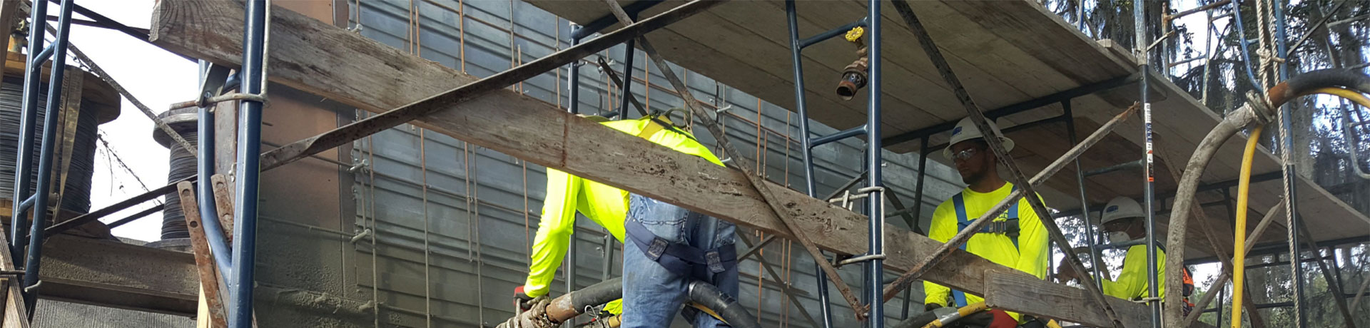
When considering placement options for thick section overhead concrete repair or strengthening, more often than not, the consideration of a shotcrete solution is overlooked. Historically, shotcrete has suffered from being mainly associated with vertical placements for above ground work. This may be due to the fact that until 1983, silica fume enhanced shotcrete was unheard of in North America; therefore, building up placement lifts overhead of more than a few inches thick using shotcrete was not deemed possible. Additionally, many shotcrete contractors customarily have avoided low production applications where placement volumes are measured in cubic yards per day rather than cubic yards per hour. As a result, most thick overhead concrete sections have been placed via the more common method of forming and pumping.
In general, forming and pumping concrete overhead works adequately. In deep sections the concrete or repair material is pumped through a port or valve on the bottom or lower side of the stout form. In effect, the air inside the form is pushed up and ultimately out of the concrete placement location. In deep section repair, there can be challenges devising a methodology that ensures no air is trapped in the upper sections of prepared areas. Repairs to pile caps may preclude the coring of vent holes down through the top of the deck due to congestion of reinforcing steel. In a form and pump application, the issue of adequate bond to the prepared concrete substrate is also a consideration. Most repair installations require a composite action of new material to existing concrete. Curing, shrinkage, and the presence of bleed water floating on top of the new concrete placement may adversely affect the ultimate bond strength of these installations. The aspect of building forms for repair and strengthening placements, especially around precast piling, can be difï¬cult and extremely time consuming as well.
Careful consideration of the pros and cons of shotcrete placement over a more traditional approach of forming and pumping for thick overhead sections offers compelling technical evidence for pursuing a shotcrete option. The following case
Shotcrete Foundation Walls at the Smithsonian Portrait Gallery in Washington, DC
The National Portrait Gallery, located on the campus of the Smithsonian Institution in Washington DC, is one of the oldest government buildings in that historic city. It was the original location for the U.S. Patent Office and it was used as the site of the inaugural ball celebrating the election of Abraham Lincoln in January 1861. When a recent renovation and expansion project was started on the building, shotcrete was selected as the material of choice
Waterproofing and Concrete Restoration at Blackwater Dam
One of the oldest dams in New England, the Blackwater Dam in Webster, NH, is located approximately 8.6 mi above the confluence of the Blackwater and Contoocook Rivers. It is part of a network of ï¬ve flood-control dams in the Merrimack River Basin that work together to control flood waters during heavy rains and storms until rivers begin to drop and the stored water can be slowly and safely released. The reservoir has a storage capacity of 15 billion gal. of water.
The U.S. Army Corps of Engineers (USACE), who oversees the property, engaged The Aulson Company to complete major concrete repairs and waterprooï¬ng to restore the dam and pedestrian walkway to peak condition after 60 years of deterioration. The USACE had made previous attempts at restoration but was not satisï¬ed with the results.
The Restoration Challenge
When the Blackwater Dam was built in 1941, the technology used to mitigate expansion and contraction was to install horizontal and vertical joints. No weepholes were provided in the original design to allow drainage back to the channel, so
Concrete Repair and Restoration at Franklin Falls Dam
The Aulson Company of Methuen, MA, completed a major concrete removal, shotcrete repair, and restoration project for the U.S. Army Corps of Engineers (USACE) at the Franklin Falls Dam, a 60-year-old structure in Franklin, NH. The Franklin Falls Dam was built by the USACE as part of a coordinated system of reservoirs to provide flood control on the Pemigewasset River Watershed of the Merrimack River Basin in the state of New Hampshire. Authorized by the Flood Control Act of 1936, the project is located on the Pemigewasset River, the main tributary of the Merrimack River, approximately 2.5 mi upstream from the city of Franklin, NH. Construction of the project began in November 1939 and was completed in October 1943. The reservoir is operated for flood control and has a total storage capacity of 154,000 acre-ft. The dam is constructed of rolled earth ï¬ll, with protective rip rap, rising 140 ft above the river bed. The spillway consists of an excavated channel along the westerly
Shotcrete Repair of WWII Concrete Hulks
In response to a shortage of plate steel during the Second World War, the United States Maritime Commission ordered 24 ships and 58 barges to be constructed with lightweight concrete. The ships were typically about 336 ft (110 m) long with a beam of 54 ft (16.5 m) and a displacement of about 11,000 tons (10,000 t). These ships and barges performed various levels of military service but typically for relatively short times due to several factors, not the least of which was the end to hostilities shortly after their launches. The useful service of these vessels (as ships and barges) was measured in months, with some being decommissioned immediately after delivery. However, at Powell River in British Columbia, Canada, as a floating breakwater and impoundment for the log storage pond, most of the surviving hulks have over 50 years of service in a saltwater environment. The Powell River floating breakwater is comprised of seven WWII steam-ships, two WWII barges, and one WWI steamship. The paper mill in Powell River acquired these ships between 1948 and 1966. After their arrival, the ships were stripped of amenities and machinery and the hulks placed in service as a breakwater.
For most of the hulks™ life as a breakwater, they were protected from direct barge impact by the numerous logs floating in the storage pond deï¬ned by the hulks. With the changing operations of the mill and the removal of the logs, the hulks became vulnerable to impact by barges also operating in the pond. This article describes the recent shotcrete repair of the impact damage to some of the hulks.
Need for Repair
While the hulks are showing deterioration related to the corrosion of the reinforcing steel due
The Setenave Dry Docks Rehabilitation
Sentenave is ageneral designation for a shipyard built in the ninty seventies at the right end of Portugal
Silica Fume in Shotcrete
Silica fume is a highly pozzolanic mineral admixture that has been used mainly to improve concrete durability and strength and as portland cement replacement. Silica fume has been used primarily in the United States, Canada, and the Scandinavian countries, but is now finding increasing use elsewhere in the world.
Shotcrete Repair Saves Baltimore Bridges
This Shotcrete Classic was selected for reader interest. While ï¬rst published 23 years ago, most of the dry-mix shotcrete technology described for repair of bridges still remains relevant today. There are a few areas where things have changed. Small line wet-mix shotcrete equipment is now available with suitable start and stop characteristics for small volume wet-mix shotcrete repair of bridges and other structures and is now also widely used for this purpose. Also, with proper surface preparation and the incorporation of silca fume in shotcrete, bonding agents are now seldom used, or needed. Good guidance regarding current recommendations for shotcrete repair of bridges can be found in the AASHTO-AGC-ARTBA Task Force 37 Report œGuide Speciï¬cation for Shotcrete Repair of Highway Bridges, published in 1998 by AASHTO in Washington, DC.
Architectural Finishes for Retaining Walls
What kind of architectural ï¬nishes are possible with shotcrete? From the most basic natural gun ï¬nish to exotic carved sculptures, from the gray color of regular portland cement concrete to custom-colored and stained mixtures, shotcrete can take on many different types of ï¬nished appearance. Today™s designers are continually challenged to provide quality finishes that ï¬t the surroundings; and in many applications, shotcrete can ï¬ll these needs. Cut and Finish Methods Achievement of an architectural ï¬nish starts with the establishment of the ï¬nal surface plane. Perimeter forms and guide wires are used to